|
|
||||||
|
||||||
3D Pose Estimationby Andrew KirillovThe article describes application of POSIT algorithm for object’s 3D pose estimation. |
Posted: July 26, 2011 Programming languages: C# AForge.NET framework: 2.2.0 |
|
Sample application (sources) – 780K Sample application (biaries) – 760K 
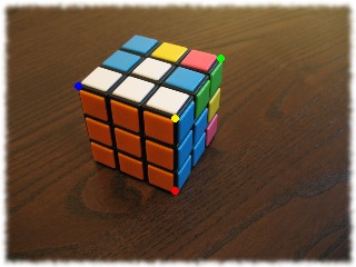
Introduction3D pose estimation of an object from its image plays important role in many different applications, like calibration, cartography, object recognition/tracking and, of course, augmented reality. The last application was of my particular interest, since I wanted to complete the glyph recognition project I did so it provides 3D augmented reality instead of 2D. There are number of research papers published about 3D pose estimation describing different algorithms. The most popular of them seems to be POSIT algorithm, which is quite easy to follow and is implemented in number of software libraries. So I did the same – implemented it in C# programming language, put that into AForge.NET framework and will describe a bit its usage. POSIT algorithmPOSIT stands for POS with ITerations, where POS stands for Pose from Orthography and Scaling. The algorithm is described in “Model-Based Object Pose in 25 Lines of Code” paper by Daniel F. DeMenthon and Larry S. Davis. Implementation of this algorithm can be found in OpenCV library, for example. Note: for those who plan to use implementation of this algorithm, a tutorial like this may be enough. However, for those who plan implementing similar in their own software/library, I would strongly recommend to read the above mentioned paper. The code provided in OpenCV as well as the pose estimation code provided in ARToolKit library is a bit cryptic and definitely will require understanding of the algorithm. So what does POSIT do? It estimates 3D pose of an object, which includes rotation over X/Y/Z axes and shift along X/Y/Z axes. How can this be used? It really depends on application. Some applications may be interested only in distance to the object, so they use X/Y/Z shifts to calculate it. Other applications may be interested only in rotation information, which can be used to control/rotate some real device. Augmented reality applications, for example, need both – they use complete transformation matrix to put a virtual 3D object on top of the image using the same rotation and translation as the real object has. What does POSIT require to be able to do 3D pose estimation? First it requires image coordinates of some object’s points (minimum 4 points). Very important to note is that these points must not be coplanar – i.e. they must not be all on the same plane. Then we need to know model coordinates of these points. This assumes that the model of the object we are estimating pose for is known, so we know coordinates of the corresponding points in the model. And finally the algorithm requires effective focal length of the camera used to picture the object. Is it too much? Let’s go through all this using some sample. Suppose we want to estimate pose of the Rubik’s Cube, like the one shown on the picture below:
First, let’s start with image coordinates of the points we are going to use for pose estimation. The image above shows 4 points colored in yellow, blue, red and green. The coordinates of the points are (all coordinates are relative to image’s center; Y axis’ positive direction is from center to top; original size of the image is 640×480):
Now we need to get model’s coordinates of these points. Let’s suppose that we have coordinate system’s center right in the center of the Rubik’s Cube and our coordinate system is left-handed. Let’s also assume that orange side of the cube is the frontal one and width of the cube’s side is 56mm. In this case we get next model coordinates of the points we selected (in millimeters):
The final thing we need is effective focal length. Image width can be taken as a good approximation of it. Since size of the example source image is 640×480, we take effective focal length equal to 640. Now we are ready to estimate pose of the Rubik’s Cube! To do so we are using Posit class from the AForge.NET Framework:
// define model
Vector3[] modelPoints = new Vector3[]
{
    new Vector3(  28,  28, -28 ),
    new Vector3( -28,  28, -28 ),
    new Vector3(  28, -28, -28 ),
    new Vector3(  28,  28,  28 )
};
// define image points
AForge.Point[] imagePoints = new AForge.Point[]
{
    new AForge.Point(   -4,   29 ),
    new AForge.Point( -180,   86 ),
    new AForge.Point(   -5, -102 ),
    new AForge.Point(   76,  137 )
};
// create instance of pose estimation algorithm
Posit posit = new Posit( modelPoints, 640 );
// estimate pose of the object
Matrix3x3 rotationMatrix;
Vector3 translationVector;
posit.EstimatePose( imagePoints, out rotationMatrix, out translationVector );
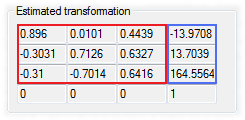
That is it – Rubik’s Cube’s pose is estimated. Now let’s have a look at the result and try to interpret it. The below 4×4 matrix contains both rotation matrix (in red) and translation vector (in blue) combined together.
The translation vector tells us that the cube’s center is ~164 mm away from camera. That it is displaced ~14 mm to left and 14 mm upper from camera’s Z axis. Obviously all these values are approximate. The algorithm tries to estimate pose only – it can not provide precise pose. Also these values highly depend on the effective focus length specified. So before relying on any of these measurements, it is recommended to do some calibration. Interpreting rotation values may not be so evident. However a method like ExtractYawPitchRoll() may help. It extracts yaw, pitch, roll ration angles from ration matrix making assumption that rotation order is roll-pitch-yaw, i.e. an object is first rotated around Z axis (roll), then around X axis (pitch) and finally around Y axis (yaw) (like OpenGL and XNA do).
float estimatedYaw;
float estimatedPitch;
float estimatedRoll;
rotationMatrix.ExtractYawPitchRoll( out estimatedYaw,
                                    out estimatedPitch,
                                    out estimatedRoll );
estimatedYaw   *= (float) ( 180.0 / Math.PI );
estimatedPitch *= (float) ( 180.0 / Math.PI );
estimatedRoll  *= (float) ( 180.0 / Math.PI );
string rotationString = string.Format(
    "Rotation: (yaw(y)={0}, pitch(x)={1}, roll(z)={2})",
    estimatedYaw, estimatedPitch, estimatedRoll );
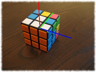
For the above shown rotation matrix the rotation angles will have next values: Rotation: (yaw(y)=34.67678, pitch(x)=-39.24732, roll(z)=-23.04074) This means that if you first rotate a Rubik’s Cube around Z axis by -23 degrees, then around X axis by -39 degrees and finally around Y axis by 34 degrees, then you should get a pose something like the one shown above. Do not believe it? Try it. Now it is time to see how the estimated pose can be used in applications like augmented reality. To demonstrate this we will put X/Y/Z axes on top of the Rubik’s Cube and make their pose to match the cube’s pose. First we’ll define model of our 3D object (3 axes), then we’ll scale it to the size of the cube (56 mm), rotate it, translate it and perform perspective projection:
// model used to draw coordinate system's axes
private Vector3[] axesModel = new Vector3[]
{
    new Vector3( 0, 0, 0 ),
    new Vector3( 1, 0, 0 ),
    new Vector3( 0, 1, 0 ),
    new Vector3( 0, 0, 1 ),
};
// transform the model and perform perspective projection
AForge.Point[] projectedAxes = PerformProjection( axesModel,
    // create tranformation matrix
    Matrix4x4.CreateTranslation( translationVector ) *        // 3: translate
    Matrix4x4.CreateFromRotation( rotationMatrix ) *          // 2: rotate
    Matrix4x4.CreateDiagonal( new Vector4( 56, 56, 56, 1 ) ), // 1: scale
    imageSize.Width );
...
private AForge.Point[] PerformProjection( Vector3[] model,
                        Matrix4x4 transformationMatrix, int viewSize )
{
    AForge.Point[] projectedPoints = new AForge.Point[model.Length];
    for ( int i = 0; i < model.Length; i++ )
    {
        Vector3 scenePoint = ( transformationMatrix *
            model[i].ToVector4( ) ).ToVector3( );
        projectedPoints[i] = new AForge.Point(
            (int) ( scenePoint.X / scenePoint.Z * viewSize ),
            (int) ( scenePoint.Y / scenePoint.Z * viewSize ) );
    }
    return projectedPoints;
}
When we have projected points of our 3D model to use for augmented reality, we just need to draw it:
// cx and cy are coordinates of image's centre
using ( Pen pen = new Pen( Color.Blue, 5 ) )
{
    g.DrawLine( pen,
        cx + projectedAxes[0].X, cy - projectedAxes[0].Y,
        cx + projectedAxes[1].X, cy - projectedAxes[1].Y );
}
using ( Pen pen = new Pen( Color.Red, 5 ) )
{
    g.DrawLine( pen,
        cx + projectedAxes[0].X, cy - projectedAxes[0].Y,
        cx + projectedAxes[2].X, cy - projectedAxes[2].Y );
}
using ( Pen pen = new Pen( Color.Lime, 5 ) )
{
    g.DrawLine( pen,
        cx + projectedAxes[0].X, cy - projectedAxes[0].Y,
        cx + projectedAxes[3].X, cy - projectedAxes[3].Y );
}
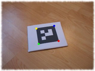
That is it! And I must admit it seems to work correctly. Yes, it is the simplest possible augmented reality – actually I would not even call it so for now. However it all depends on the size of model drawn on top of the picture. Someone may say that the X/Y/Z axes are drawn incorrectly – they must start from the center of the cube, but not from its edge. Actually they seem to start from the center. It is just 2D picture so it is hard to do much about it. As you can see all 3 axes go very closely through centers of corresponding sides, which means they need to start somewhere in the center of the cube. Also, as I mentioned before, calibration of effective focal length may help. Coplanar POSIT algorithmAlthough POSIT algorithm seems to work quite well, it has one limitation, which does not allow its usage in most augmented reality applications. The limitation comes from the fact that points of the model we want to estimate pose for must not be coplanar, i.e. points we use for pose estimation are not allowed to be on one plane. However most augmented reality applications are based on detection of optical glyphs, which are obviously plane. For example, if use an object similar to the one shown on the picture below and provide its image points and corresponding model to POSIT algorithm, it will not provide any good result.
Fortunately the topic of estimating pose of an object with coplanar points is known and there are research papers about it as well. The algorithm which solves this problem is known as Coplanar POSIT and is described in “Iterative Pose Estimation using Coplanar Feature Points” paper written by Oberkampf, Daniel F. DeMenthon and Larry S. Davis. The Coplanar POSIT algorithm is also implemented in AForge.NET framework – see CoplanarPosit class. From user’s stand point of view its usage is almost the same – also specify model and focal length and then perform pose estimation for certain image points:
// define model of glyph with side length equal to 113 mm
Vector3[] modelPoints = new Vector3[]
{
    new Vector3( -56.5f, 0,  56.5f ),
    new Vector3(  56.5f, 0,  56.5f ),
    new Vector3(  56.5f, 0, -56.5f ),
    new Vector3( -56.5f, 0, -56.5f ),
};
// define image points
AForge.Point[] imagePoints = new AForge.Point[]
{
    new AForge.Point( -77,  48 ),
    new AForge.Point(  44,  66 ),
    new AForge.Point(  75, -36 ),
    new AForge.Point( -61, -58 ),
};
// create instance of pose estimation algorithm
CoplanarPosit coposit = new CoplanarPosit( modelPoints, 640 );
// estimate pose of the object
Matrix3x3 rotationMatrix;
Vector3 translationVector;
coposit.EstimatePose( imagePoints, out rotationMatrix, out translationVector );
Applying obtained rotation matrix and translation vector to some 3D model (X/Y/Z axes as before) will give result like this:
The only difference between POSIT and Coplanar POSIT algorithms for user is the fact that Coplanar POSIT algorithm provides 2 estimations of object’s pose – there are two solutions of equations system for coplanar version of the algorithm. The only way to check which pose estimation is better is to apply both estimated transformations to the model, perform perspective projection and compare with provided image points. The pose estimation which leads to similar image points is supposed to be best. Note: all this is done by Coplanar POSIT algorithm’s implementation automatically, so it provides the best estimation. However, if user needs it, the alternate estimation is also available (see documentation to CoplanarPosit class). ConclusionAs we can see from all the above the pose estimation algorithms seem to do their job quite well. The only uncertain parameter may be the effective focal length, but it can be calibrated before starting with augmented reality or anything else where we may need 3D pose estimation. In order to play and experiment with these algorithms, there are 2 sample applications provided with the article (see links on top). Both applications are also available as part of AForge.NET Framework samples’ collection. The first application is mostly for testing of these algorithms – it just performs perspective projection of some model which user can move/rotate and then uses these projected points to estimate pose of the model. The second application allows user to estimate pose of some object on images – just select points of interest on any image, define model and try estimating its pose (sample images and models are built into the sample). |
|||||||
|
|
|||||||