|
|
||||||
|
||||||
3D Augmented Realityby Andrew KirillovThe article describes an approach of making 3D augmented reality based on glyph recognition. |
Posted: September 20, 2011 Programming languages: C# AForge.NET framework: 2.2.2 |
IntroductionIt’s been a while since I did my very first attempt in augmented reality when doing the glyph recognition project described last year. Although it worked nice, that time it was nothing more than 2D augmented reality – just a picture put on place of the recognized glyph. As it turned out, just detecting and recognizing a glyph is not enough to put a 3D object on top of it. In order to do that it is also required to estimate pose of a glyph in the real world, so its rotation and translation are known. This can be done using POSIT algorithms, which were described recently. So, when we got the missing part, it is time to complete the project and get some 3D augmented reality out of it. I’ll start from 3D rendering first, so when we get to glyphs’ pose estimation and augmented reality we already have some understanding of the API allowing to render 3D models. 3D renderingOne of the first things to start from is to decide which library/framework to use for 3D rendering. For this augmented reality project I decided to try Microsoft’s XNA framework. Note: since the main topic of this article is not related to XNA, a beginners’ introduction into XNA will not be part of it. Since XNA framework is targeted to games development mostly, its integration with WinForms applications was not something straight forward from its very first release. The idea was that XNA manages entire game’s window, graphics and input/output. However things have improved since that time and there are official samples exist showing integration of XNA into WinForms applications. Following some of those XNA samples and tutorials, it will become clear at some point in time that a simple code for rendering a small model may look something like this:
protected override void Draw( )
{
    GraphicsDevice.Clear( Color.Black );
    // draw simple models for now with single mesh
    if ( ( model != null ) && ( model.Meshes.Count == 1 ) )
    {
        ModelMesh mesh = model.Meshes[0];
        // spin the object according to how much time has passed
        float time = (float) timer.Elapsed.TotalSeconds;
        // object's rotation and transformation matrices
        Matrix rotation = Matrix.CreateFromYawPitchRoll(
            time * 0.5f, time * 0.6f, time * 0.7f );
        Matrix translation = Matrix.CreateTranslation( 0, 0, 0 );
        // create transform matrices
        Matrix viewMatrix = Matrix.CreateLookAt(
            new Vector3( 0, 0, 3 ), Vector3.Zero, Vector3.Up );
        Matrix projectionMatrix = Matrix.CreatePerspective(
            1, 1 / GraphicsDevice.Viewport.AspectRatio, 1f, 10000 );
        Matrix world = Matrix.CreateScale( 1 / mesh.BoundingSphere.Radius ) *
            rotation * translation;
        foreach ( Effect effect in mesh.Effects )
        {
            if ( effect is BasicEffect )
            {
                ( (BasicEffect) effect ).EnableDefaultLighting( );
            }
            effect.Parameters["World"].SetValue( world );
            effect.Parameters["View"].SetValue( viewMatrix );
            effect.Parameters["Projection"].SetValue( projectionMatrix );
        }
        mesh.Draw( );
    }
}
How much will the above code differ from the complete AR rendering? It will not be different too much actually. The above code is missing only 2 things to get some augmented reality out of it: 1) draw real scene instead of filling it with black color; 2) use proper world transformation matrix (scaling, rotation and transformation) for the virtual object to put onto a glyph. That’s it – just 2 things. For the augmented reality scene we need to render pictures of real world – video coming from camera, file or any other source and containing some optical glyphs to recognize. Without going into video acquisition/reading details, we can just assume that every new video frame is provided as .NET’s Bitmap. Apparently XNA framework does not care too much about GDI+ bitmaps and does not provide means for rendering those. So we need a tool method, which allows converting Bitmap into XNA’s 2D texture to render:
// Convert GDI+ bitmap to XNA texture
public static Texture2D XNATextureFromBitmap( Bitmap bitmap, GraphicsDevice device )
{
    int width  = bitmap.Width;
    int height = bitmap.Height;
    Texture2D texture = new Texture2D( device, width, height,
        1, TextureUsage.None, SurfaceFormat.Color );
    BitmapData data = bitmap.LockBits( new Rectangle( 0, 0, width, height ),
        ImageLockMode.ReadOnly, PixelFormat.Format32bppArgb );
    int bufferSize = data.Height * data.Stride;
    // copy bitmap data into texture
    byte[] bytes = new byte[bufferSize];
    Marshal.Copy( data.Scan0, bytes, 0, bytes.Length );
    texture.SetData( bytes );
    bitmap.UnlockBits( data );
    return texture;
}
Once a bitmap containing current video frame is converted to XNA’s texture, it can be rendered before rendering 3D models, so those sit on top of some real world picture instead of black background. The only important thing to note is that after doing some 2D rendering it is required to restore some states of the XNA graphics device, which are shared between 2D and 3D graphics, but changed by texture rendering for its purposes. // draw texture containing video frame mainSpriteBatch.Begin( SpriteBlendMode.None ); mainSpriteBatch.Draw( texture, new Vector2( 0, 0 ), Color.White ); mainSpriteBatch.End( ); // restore state of some graphics device's properties after 2D graphics, // so 3D rendering will work fine GraphicsDevice.RenderState.DepthBufferEnable = true; GraphicsDevice.RenderState.AlphaBlendEnable = false; GraphicsDevice.RenderState.AlphaTestEnable = false; GraphicsDevice.SamplerStates[0].AddressU = TextureAddressMode.Wrap; GraphicsDevice.SamplerStates[0].AddressV = TextureAddressMode.Wrap; The last and the most important part is to make sure that size, position and rotation of the rendered model correspond to the pose and position of a glyph existing in the real world. All this is not complex at this point, since it was all described in previous articles already. Now we just need to combine that all together. Bringing optical glyph from real to virtual worldAs we remember from the previous article, the glyph recognition algorithm provides coordinates of 4 corners for each detected and recognized glyph. These are only X/Y image coordinates of 4 corners. But for putting a 3D model on top of a glyph, we need to know its real world coordinates, which include glyph’s translation and rotation. This can be estimated using the Coplanar POSIT algorithm described previously. To use pose estimation algorithm we just need to define real world model of a glyph and we are ready to go. For example, let’s suppose that our glyph’s width/height is 113 mm (glyphs are square objects). So if we put glyph’s center into origin of coordinate system and make it lying in XZ plane, then model can be defined with 4 points like this:
The last thing to mention is that coordinates of 4 glyph’s points also need to be recalculated to be relative to image’s center and converted from image’s coordinate system with Y-axis going down to coordinate system with Y-axis going up. Translating all the above into code should give the next pose estimation routine:
// define glyph's model
float sizeHalf = 113.0f / 2;
Vector3[] glyphModel = new Vector3[]
{
    new Vector3( -sizeHalf, 0,  sizeHalf ),
    new Vector3(  sizeHalf, 0,  sizeHalf ),
    new Vector3(  sizeHalf, 0, -sizeHalf ),
    new Vector3( -sizeHalf, 0, -sizeHalf ),
};
// convert glyph's coordinates
Point[] glyphPoints = new Point[4];
for ( int i = 0; i < 4; i++ )
{
    glyphPoints[i] = new Point(
        glyph.RecognizedQuadrilateral[i].X - imageCenterX,
        imageCenterY - glyph.RecognizedQuadrilateral[i].Y );
}
// create pose estimation algorithm
CoplanarPosit posit = new CoplanarPosit( glyphModel, cameraFocalLength );
// estimate glyph's pose
Matrix3x3 positRotation;
Vector3 positTranslation;
posit.EstimatePose( glyphPoints, out positRotation, out positTranslation );
Now when we have glyph’s rotation and translation known, we can update the XNA part to use this information in order to put 3D model into correct place and use proper rotation and size for it. Here is the part of the code (copied from initial XNA code sample) which calculates model’s world matrix for XNA rendering – we will need to change this part only to complete augmented reality scene, since we already have all the rest:
...
Matrix world = Matrix.CreateScale( 1 / mesh.BoundingSphere.Radius ) *
    rotation * translation;
...
Someone potentially may think that converting AForge.NET framework’s matrices/vectors to XNA’s matrices should be enough to get everything working. However it is not. Although XNA uses column wise matrix representation, but AForge.NET framework uses row wise it is not the major difference to take care of. What we need to take care is the fact that XNA uses different coordinate system from the one used by pose estimation code. XNA uses right-handed coordinate system, where Z axis is directed from origin to viewer when X and Y axes are directed to right and up respectively. In such coordinates system increasing Z coordinate of an object makes it closer to viewer (camera), which makes it look bigger on projected screen. However in real world we have the opposite case – larger Z coordinate of an object means it is further away from viewer. This is known as left-handed coordinate system, when Z axis points away from viewer and X/Y axes have the same direction (right/up). So we need to convert glyph’s estimated pose coordinates from left-handed to right-handed system. The first part of conversion real world’s coordinates to XNA’s is to negate object’s Z coordinate, so the further away an object in real world – the deeper it is in XNA scene. And the second part is to convert object’s rotation angles – negate rotation around X and Y axes. One more important thing – we need to scale XNA’s 3D model. As we’ve seen above, we described glyph’s model in millimeters. So pose estimation algorithm estimated glyph’s translation also in millimeters. This will result in model’s Z coordinate set to ~ -200, when a glyph is about 20 centimeters away from camera, which will make 3D model look tiny on XNA scene if model’s original size is small. So all we need to do is just to scale 3D model, so it has “comparable” size to the glyph’s size. Putting all this together will replace the above mentioned line of code (which computes XNA object’s world matrix) with the next code:
float modelSize = 113;
// extract rotation angles from the estimated rotation
float yaw, pitch, roll;
positRotation.ExtractYawPitchRoll( out yaw, out pitch, out roll );
// create XNA's rotation matrix
Matrix rotation = Matrix.CreateFromYawPitchRoll( -yaw, -pitch, roll );
// create XNA's translation matrix
Matrix translation = Matrix.CreateTranslation(
    positTranslation.X, positTranslation.Y, -positTranslation.Z );
// create scaling matrix, so model fits its glyph
Matrix scaling = Matrix.CreateScale( modelSize );
// finally compute XNA object's world matrix
Matrix world = Matrix.CreateScale( 1 / mesh.BoundingSphere.Radius ) *
    scaling * rotation * translation;
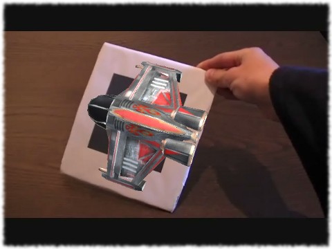
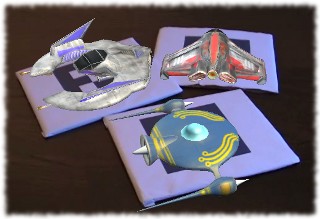
Well, that is it – augmented reality is done. With all the above code put together we should get an XNA screen like this:
Few things behind the sceneAlthough all the above is enough to get 3D augmented reality, there are few things which may be worth of mentioning. One thing is related to “noise” in glyph’s corners detection which was described before. If you take a closer look at one of the videos published previously, you may notice that in some cases corners of some glyphs may do kind of shaking (moving one-two pixels) although the entire glyph is supposed to be static. This glyph shaking effect can be caused by different factors – noise in video stream, noise in illumination, artifacts of video compression, etc. All these factors lead to small errors in detection of glyphs’ corners, which may vary by few pixels between consequent video frames. This type of glyph’s shaking is not an issue for those applications which require glyph detection/recognition only. But in augmented reality applications small errors like this may cause some unwanted visual effects which don’t look nice. As it can be seen on the previous videos, the one-pixel change in glyph’s coordinates already makes a shaking picture in 2D augmented reality. In 3D augmented reality this would be even worse, since a small change in few pixels will lead to a bit different estimation of 3D pose, which will make 3D model to shake even more. To eliminate the above described noise in corners detection leading to AR model shaking, it is possible to implement glyphs’ coordinates tracking. For example, if maximum change in all 8 coordinates of glyph’s corners is 2 pixels or more, than the glyph is supposed to be moving. Otherwise, when maximum change is 1 pixel only, it is treated as noise and glyph’s previous coordinates are used. One more check which can be done is to count number of corners, which changed its position by more than 1 pixel. If it is only one such corner, then it is also treated as noise. This rule is caused by the assumption that it is hardly possible to rotate a glyph in such way, that after perspective projection only one corner will change its position. Another issue which may cause some 3D augmented realty artifacts is related to 3D pose estimation using Coplanar POSIT algorithm. As it is said in description of the algorithm, its math may come up with two valid estimations of 3D pose (valid from the math point of view). Of course both estimations are examined to find how well they are and error value is calculated for each estimation. However error values for both estimations may be quite small and potentially a wrong estimation may get lower error (again due to noise and imperfection in corners detection) on one of the video frames. This may produce bad looking effect in augmented reality, when most of the time a 3D model is displayed correctly, but from time to time its pose changes to something completely different. The above mentioned 3D pose estimation errors also can be handled by tracking glyph’s pose. For example, if best estimated pose has error value which is twice (or more) less than the error of alternate pose, then such pose is always believed to be correct. However, if difference in error values for both poses is small, then the tracking algorithm selects the pose, which seems to be closer to the glyph’s pose detected on the previous video frame. (Note: code samples for the above described tracking routines are skipped in the article and can be found in complete source code of the GRATF project) The final resultAnd now it is time for the final video of 3D augmented reality with all the noise suppression and 3D pose corrections … Application and source codeAs you’ve noticed there are no any attachments to this article – no source code, no pre-built sample applications, nothing else. That is because all this is available in GRATF project, where all the code, samples and additional information can be obtained. In order to get 3D augmented reality working, you will need to get at least 2.0.0 version of GRATF. ConclusionIt took me a while to complete the project from its very first stage, when a glyph recognition algorithm was prototyped, till the final result, which is the 3D augmented reality. But I must admit I enjoyed doing it and learned a lot, especially taking into account that most of it was done from scratch – just brainstorming about the algorithms, looking for bits of knowledge around the Internet, etc. Could it be done quicker? Sure. For me it was just a hobby project driven when time permits. At this point the GRATF project, which accumulates all the results of the work being done, consists of the 2 main parts: 1) a glyph localization, recognition and pose estimation library and 2) a Glyph Recognition Studio application, which shows all in action including 2D/3D augmented reality. Since the core algorithms are put outside into a library, it makes them easy to integrate and use in another application, which requires either glyph recognition only or something more like augmented reality. Although it was done a lot to get it working, there is still more to continue in order to improve it. For example, one of the crucial areas is glyph detection/recognition. At this point the algorithm may fail to detect a glyph if it moves too fast for current illumination conditions and camera’s exposure time. In this case glyph’s image gets blurred making it hard to do any recognition with it. Further improvement could be done in 3D pose estimation algorithms. And of course there is a lot can be done about tracking glyphs. For example, it could be possible to calculate glyph’s movement/rotation velocity and acceleration along 3 axes, which could be used for making some nice 3D games and effects. I really hope this article (and the previous one on this topic) will find its readers and the project will find its users, so the work could be reused and extended to bring new cool applications. |
||||
|
|
||||